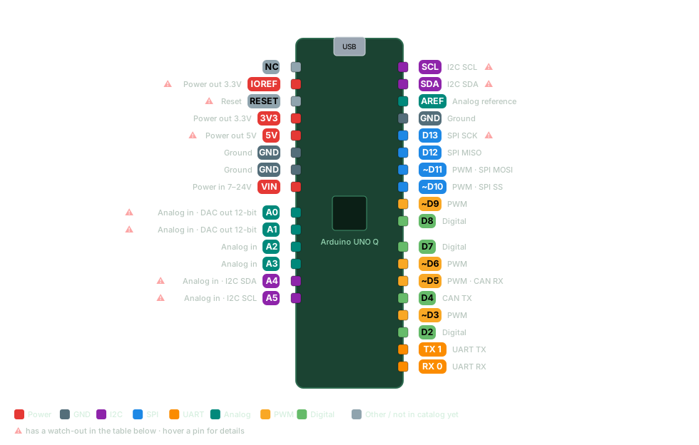
Every Arduino UNO Q pin with its capabilities (digital, PWM, ADC, I2C, SPI, UART) and the wiring gotchas that bite. Two brains in an UNO footprint: a quad-core Linux computer for AI/vision work talking to a real-time STM32 that owns the classic headers. The headers are 3.3 V, not 5 V.
Qwiic connector on the edge; the Linux side has its own USB-C. Download SVG
Pin
Capabilities
Watch out
D0 (RX)
DigitalUART RX
D1 (TX)
DigitalUART TX
D2
Digital
~D3
DigitalPWM
D4
DigitalCAN TX
~D5
DigitalPWMCAN RX
~D6
DigitalPWM
D7
Digital
D8
Digital
~D9
DigitalPWM
~D10
DigitalPWMSPI SS
~D11
DigitalPWMSPI MOSI
D12
DigitalSPI MISO
D13
DigitalSPI SCK
No LED_BUILTIN here — the user LEDs are four RGB LEDs and the 8x13 matrix
D20
DigitalI2C SDA
Header I2C lives here, not on A4/A5
D21
DigitalI2C SCL
Header I2C lives here, not on A4/A5
AREF
Analog reference
A0
Analog inDAC out 12-bit
Direct ADC input — NOT 5 V tolerant (max ~3.6 V)
A1
Analog inDAC out 12-bit
Direct ADC input — NOT 5 V tolerant (max ~3.6 V)
A2
Analog in
A3
Analog in
A4
Analog inI2C SDA
This is I2C3, a different bus from the D20/D21 header I2C
A5
Analog inI2C SCL
This is I2C3, a different bus from the D20/D21 header I2C
IOREF
Power out 3.3V
Mirrors the 3.3 V rail — output only, never feed power back in
3V3
Power out 3.3V
5V
Power out 5V
Pass-through from USB VBUS — power only, not a logic level
VIN
Power in 7–24V
RESET
Reset
Resets the STM32 only — not the Linux side
GND
Ground
Arduino UNO Q gotchas & notes
DUAL-BRAIN: a Qualcomm QRB2210 (4x Cortex-A53 @ 2.0 GHz) runs Debian Linux; an STM32U585 (Cortex-M33) runs your sketch on Zephyr. They talk over Arduino's Bridge RPC library.
The header pins listed here all belong to the STM32 — it owns JDIGITAL, JANALOG, JSPI, Qwiic, plus ADC, PWM, CAN and the LED matrix. The Linux side's own GPIO sits on separate headers at 1.8 V.
3.3 V LOGIC — the UNO shield footprint fits, but 5 V shields and sensors do NOT. A0/A1 are direct ADC inputs and are not 5 V tolerant (absolute max ~3.6 V); check every shield before stacking.
I2C IS NOT ON A4/A5 THE WAY YOU EXPECT: the header I2C is D20 (SDA) / D21 (SCL) on I2C2, Qwiic is a separate I2C4 bus, and A4/A5 carry I2C3.
PWM (analogWrite) on the pins marked ~: 3, 5, 6, 9, 10, 11. A0 and A1 are also true 12-bit DAC outputs, so they can put out a real analog voltage.
The STM32 is a Cortex-M33, so external interrupts are available on essentially any GPIO — not just two pins like on the UNO.
The 'AI' is software on the Linux side (Arduino App Lab), running on CPU/GPU — there is no dedicated NPU on the QRB2210.
Power: USB-C PD (asks for 5 V 3 A) or 7-24 V on VIN. The 8x13 blue LED matrix shows the boot logo for 20-30 s; touching it before Linux finishes booting can upset the MCU.
Two variants: 2 GB RAM / 16 GB eMMC (ABX00162) and 4 GB / 32 GB (ABX00173). The 4 GB one is what Arduino recommends if you run App Lab on the board itself.
Get this pinout — plus 55+ sensor wiring diagrams, shield maps and maker calculators — offline on your phone.