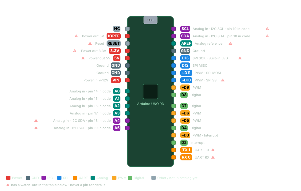
Every Arduino UNO R3 pin with its capabilities (digital, PWM, ADC, I2C, SPI, UART) and the wiring gotchas that bite. The classic beginner board. 5 V logic, forgiving, huge library support.
ATmega328P @ 16 MHzLogic: 5 VFree in app
Arduino UNO R3 pinout diagram
ICSP (2x3, bottom edge): MISO · 5V · SCK · MOSI · RESET · GND. Second 2x3 near the USB port is the 16U2's. Download SVG
Pin
Capabilities
Watch out
D0 (RX)
DigitalUART RX
Shared with USB serial
D1 (TX)
DigitalUART TX
Shared with USB serial
D2
DigitalInterrupt
D3
DigitalPWMInterrupt
D4
Digital
D5
DigitalPWM
D6
DigitalPWM
D7
Digital
D8
Digital
D9
DigitalPWM
D10
DigitalPWMSPI SS
SS is convention, not hardwired — any output pin can be chip select. But keep D10 an OUTPUT whenever SPI is master, or the hardware drops into slave mode
D11
DigitalPWMSPI MOSI
D12
DigitalSPI MISO
D13
DigitalSPI SCKBuilt-in LED
The L LED loads this pin; also on the ICSP header
A0
Analog inDigitalpin 14 in code
A1
Analog inDigitalpin 15 in code
A2
Analog inDigitalpin 16 in code
A3
Analog inDigitalpin 17 in code
A4
Analog inDigitalI2C SDApin 18 in code
Using it as GPIO takes out I2C
A5
Analog inDigitalI2C SCLpin 19 in code
Using it as GPIO takes out I2C
AREF
Analog reference
Call analogReference(EXTERNAL) before feeding a voltage in, or it shorts against the internal reference
IOREF
Power out 5V
Logic-level reference for shields — output only, never feed power in
RESET
Reset
Active LOW — pull to GND to reset; shield reset buttons land here
A0–A5 double as digital pins 14–19: write 14 (or A0) in a sketch, not D14 — that name isn't defined on AVR boards. A4/A5 included, but using them as GPIO takes out I2C.
Pins 0/1 are the USB serial — avoid using them while Serial is active.
External interrupts (attachInterrupt) are only on D2 (INT0) and D3 (INT1); every other I/O pin supports pin-change interrupts (PCINT) via the PCICR/PCMSK registers or a library.
ICSP header (2x3): MISO, MOSI, SCK, RESET, 5V, GND — the same SPI lines as D11–D13. Used to burn the bootloader; some shields take SPI from here so they also work on a Mega. The second 2x3 header near USB is for the ATmega16U2, not the 328P.
On-board LEDs: ON = 5 V rail present; L = tied to D13; TX/RX blink on USB serial traffic only (driven by the 16U2, not by D0/D1).
Get this pinout — plus 55+ sensor wiring diagrams, shield maps and maker calculators — offline on your phone.