Raspberry Pi Pico pinout
Every Raspberry Pi Pico pin with its capabilities (digital, PWM, ADC, I2C, SPI, UART) and the wiring gotchas that bite. Cheap, fast, with PIO state machines. 3.3 V logic — GPIOs are NOT 5 V tolerant.
RP2040 dual-core M0+ @ 133 MHz Logic: 3.3 V Pro in app
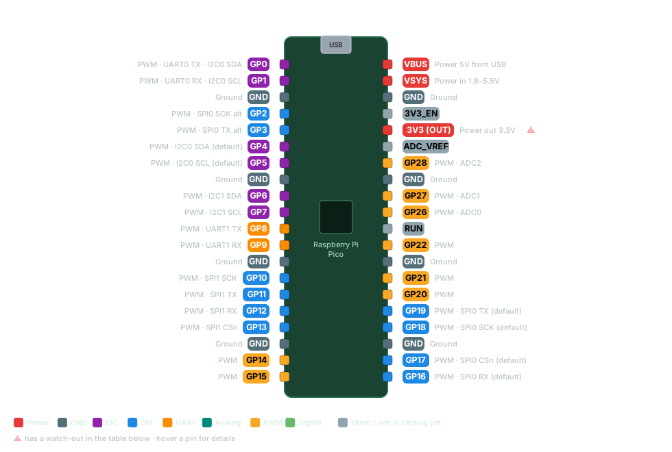
Raspberry Pi Pico pinout diagram Raspberry Pi Pico (RP2040) pinout diagram USB Raspberry Pi Pico GP0: PWM · UART0 TX · I2C0 SDA GP0 PWM · UART0 TX · I2C0 SDA GP1: PWM · UART0 RX · I2C0 SCL GP1 PWM · UART0 RX · I2C0 SCL GND: Ground GND Ground GP2: PWM · SPI0 SCK alt GP2 PWM · SPI0 SCK alt GP3: PWM · SPI0 TX alt GP3 PWM · SPI0 TX alt GP4: PWM · I2C0 SDA (default) GP4 PWM · I2C0 SDA (default) GP5: PWM · I2C0 SCL (default) GP5 PWM · I2C0 SCL (default) GND: Ground GND Ground GP6: PWM · I2C1 SDA GP6 PWM · I2C1 SDA GP7: PWM · I2C1 SCL GP7 PWM · I2C1 SCL GP8: PWM · UART1 TX GP8 PWM · UART1 TX GP9: PWM · UART1 RX GP9 PWM · UART1 RX GND: Ground GND Ground GP10: PWM · SPI1 SCK GP10 PWM · SPI1 SCK GP11: PWM · SPI1 TX GP11 PWM · SPI1 TX GP12: PWM · SPI1 RX GP12 PWM · SPI1 RX GP13: PWM · SPI1 CSn GP13 PWM · SPI1 CSn GND: Ground GND Ground GP14: PWM GP14 PWM GP15: PWM GP15 PWM VBUS: Power 5V from USB VBUS Power 5V from USB VSYS: Power in 1.8–5.5V VSYS Power in 1.8–5.5V GND: Ground GND Ground 3V3_EN (not detailed in the catalog yet) 3V3_EN 3V3 (OUT): Power out 3.3V. Watch out: Max ~300 mA 3V3 (OUT) Power out 3.3V ⚠ ADC_VREF (not detailed in the catalog yet) ADC_VREF GP28: PWM · ADC2 GP28 PWM · ADC2 GND: Ground GND Ground GP27: PWM · ADC1 GP27 PWM · ADC1 GP26: PWM · ADC0 GP26 PWM · ADC0 RUN (not detailed in the catalog yet) RUN GP22: PWM GP22 PWM GND: Ground GND Ground GP21: PWM GP21 PWM GP20: PWM GP20 PWM GP19: PWM · SPI0 TX (default) GP19 PWM · SPI0 TX (default) GP18: PWM · SPI0 SCK (default) GP18 PWM · SPI0 SCK (default) GND: Ground GND Ground GP17: PWM · SPI0 CSn (default) GP17 PWM · SPI0 CSn (default) GP16: PWM · SPI0 RX (default) GP16 PWM · SPI0 RX (default) Power GND I2C SPI UART Analog PWM Digital Other / not in catalog yet ⚠ has a watch-out in the table below · hover a pin for details
Pin Capabilities Watch out GP0 Digital PWM UART0 TX I2C0 SDA GP1 Digital PWM UART0 RX I2C0 SCL GP2 Digital PWM SPI0 SCK alt GP3 Digital PWM SPI0 TX alt GP4 Digital PWM I2C0 SDA (default) GP5 Digital PWM I2C0 SCL (default) GP6 Digital PWM I2C1 SDA GP7 Digital PWM I2C1 SCL GP8 Digital PWM UART1 TX GP9 Digital PWM UART1 RX GP10 Digital PWM SPI1 SCK GP11 Digital PWM SPI1 TX GP12 Digital PWM SPI1 RX GP13 Digital PWM SPI1 CSn GP14 Digital PWM GP15 Digital PWM GP16 Digital PWM SPI0 RX (default) GP17 Digital PWM SPI0 CSn (default) GP18 Digital PWM SPI0 SCK (default) GP19 Digital PWM SPI0 TX (default) GP20 Digital PWM GP21 Digital PWM GP22 Digital PWM GP26 Digital PWM ADC0 GP27 Digital PWM ADC1 GP28 Digital PWM ADC2 3V3 (OUT) Power out 3.3V Max ~300 mA
VBUS Power 5V from USB VSYS Power in 1.8–5.5V GND Ground
Raspberry Pi Pico gotchas & notes Every GPIO supports PWM. Default I2C0: SDA=GP4, SCL=GP5. Default SPI0: RX/MISO=GP16, CSn=GP17, SCK=GP18, TX/MOSI=GP19. Analog inputs: GP26 (ADC0), GP27 (ADC1), GP28 (ADC2). ADC3 reads VSYS internally. VBUS = USB 5 V; 3V3(OUT) can supply up to ~300 mA to peripherals. Onboard LED is GP25 (on the W variant it's driven via the WiFi chip). Get this pinout — plus 55+ sensor wiring diagrams, shield maps and maker calculators — offline on your phone.
Get it on Google Play Other board pinouts