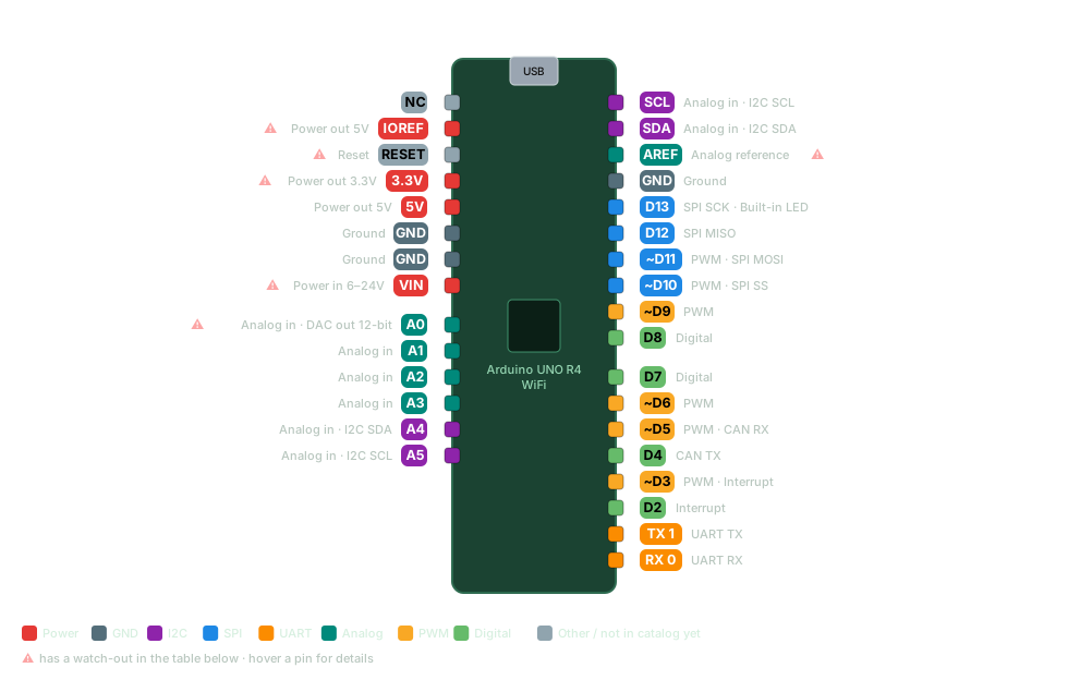
Arduino UNO R4 WiFi pinout
Every Arduino UNO R4 WiFi pin with its capabilities (digital, PWM, ADC, I2C, SPI, UART) and the wiring gotchas that bite. The modern UNO: still 5 V and shield-compatible, but with WiFi/Bluetooth, a real DAC, CAN bus and a 12x8 LED matrix on board.
Renesas RA4M1 @ 48 MHz + ESP32-S3 (WiFi/BLE) Logic: 5 V Free in app
Arduino UNO R4 WiFi pinout diagram Arduino UNO R4 WiFi pinout diagram USB Arduino UNO R4 WiFi NC (not detailed in the catalog yet) NC IOREF: Power out 5V. Watch out: Logic-level reference for shields — output only IOREF Power out 5V ⚠ RESET: Reset. Watch out: Active LOW RESET Reset ⚠ 3.3V: Power out 3.3V. Watch out: Lower current than the 5V rail 3.3V Power out 3.3V ⚠ 5V: Power out 5V 5V Power out 5V GND: Ground GND Ground GND: Ground GND Ground VIN: Power in 6–24V. Watch out: R4 accepts up to 24V on VIN VIN Power in 6–24V ⚠ A0: Analog in · DAC out 12-bit. Watch out: True analog output — not on other UNO pins A0 Analog in · DAC out 12-bit ⚠ A1: Analog in A1 Analog in A2: Analog in A2 Analog in A3: Analog in A3 Analog in A4: Analog in · I2C SDA A4 Analog in · I2C SDA A5: Analog in · I2C SCL A5 Analog in · I2C SCL SCL = A5: Analog in · I2C SCL SCL Analog in · I2C SCL SDA = A4: Analog in · I2C SDA SDA Analog in · I2C SDA AREF: Analog reference. Watch out: Only feed a reference in after analogReference(AR_EXTERNAL) AREF Analog reference ⚠ GND: Ground GND Ground D13: SPI SCK · Built-in LED D13 SPI SCK · Built-in LED D12: SPI MISO D12 SPI MISO ~D11 = D11: PWM · SPI MOSI ~D11 PWM · SPI MOSI ~D10 = D10: PWM · SPI SS ~D10 PWM · SPI SS ~D9 = D9: PWM ~D9 PWM D8: Digital D8 Digital D7: Digital D7 Digital ~D6 = D6: PWM ~D6 PWM ~D5 = D5: PWM · CAN RX ~D5 PWM · CAN RX D4: CAN TX D4 CAN TX ~D3 = D3: PWM · Interrupt ~D3 PWM · Interrupt D2: Interrupt D2 Interrupt TX 1 = D1 (TX): UART TX TX 1 UART TX RX 0 = D0 (RX): UART RX RX 0 UART RX Power GND I2C SPI UART Analog PWM Digital Other / not in catalog yet ⚠ has a watch-out in the table below · hover a pin for details
Pin Capabilities Watch out D0 (RX) Digital UART RX D1 (TX) Digital UART TX D2 Digital Interrupt D3 Digital PWM Interrupt D4 Digital CAN TX D5 Digital PWM CAN RX D6 Digital PWM D7 Digital D8 Digital D9 Digital PWM D10 Digital PWM SPI SS D11 Digital PWM SPI MOSI D12 Digital SPI MISO D13 Digital SPI SCK Built-in LED A0 Analog in DAC out 12-bit True analog output — not on other UNO pins
A1 Analog in Digital A2 Analog in Digital A3 Analog in Digital A4 Analog in Digital I2C SDA A5 Analog in Digital I2C SCL AREF Analog reference Only feed a reference in after analogReference(AR_EXTERNAL)
IOREF Power out 5V Logic-level reference for shields — output only
RESET Reset Active LOW
5V Power out 5V 3.3V Power out 3.3V Lower current than the 5V rail
VIN Power in 6–24V R4 accepts up to 24V on VIN
GND Ground
Arduino UNO R4 WiFi gotchas & notes 5 V logic and the classic UNO footprint — existing shields and 5 V modules still work. A0 is a true 12-bit DAC (analogWrite to A0 outputs an analog voltage), not just PWM. WiFi and Bluetooth are handled by an onboard ESP32-S3; use the WiFiS3 library. Qwiic/STEMMA I2C connector on board; SDA/SCL also on A4/A5. PWM (analogWrite) on ~3, 5, 6, 9, 10, 11. Get this pinout — plus 55+ sensor wiring diagrams, shield maps and maker calculators — offline on your phone.
Get it on Google Play Other board pinouts